
Monday, 21 April 2014

Sunday, 2 February 2014
Saturday, 1 February 2014
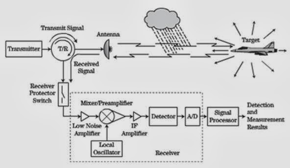
Radar is an Electromagnetic system for detecting and locating reflecting objects such as aircraft,ships,spacecraft,vehicles,people and natural environment.Radars system is such a classic system that includes all domain of electronics engineering control system such as
•Electromagnetic
•Analog & Digital Electronics•Analog & Digital Communication•Microwave & Radiating Systems•Transmitters & Receivers •Signals &Data processing•Control Systems•Information & Detection Theory
•Analog & Digital Electronics•Analog & Digital Communication•Microwave & Radiating Systems•Transmitters & Receivers •Signals &Data processing•Control Systems•Information & Detection Theory
The Basic Concept of Radar:
Tuesday, 28 January 2014
My Air Craft for Modifications
Something about my Aircraft B-737-400
Crew 2
Passengers 146 / 159, max. 189
Propulsion 2 Turbofan Engines
Engine Model CFM Intl. CFM56-3B2, CFM56-3C
Engine Power (each) 98 / 105 kN 22000 / 23500 lbf
Speed 933 km/h 504 kts
580 mph
Mmo (max. Mach) Mach 0.82
Service Ceiling 11.278 m 37.000 ft
Range 5.186 km 2.800 NM 3.222 mi.
Empty Weight 33.650 kg 74.185 lbs
max. Takeoff Weight 68.039 kg 150.000 lbs
max. Landing Weight 56.246 kg 124.000 lbs
Wing Span 28,88 m 94,8 ft
Wing Area 105,4 m² 1135 ft²
Length 36,40 m 119,4 ft
Height 11,07 m 36,3 ft
First Flight 19.02.1988
Production Range 1988-2000
Total Production 486

Courtesy of British Airways
Friday, 24 January 2014
Instrument Landing System ( ILS) (A synopsis)
Instrument Landing System ( ILS)
- ILS is the only Navigational Aid for Landing and final Approach having two transmitters installed at far end of the Runway.This is system that uses VHF & UHF radio waves. ILS has been in usage since 1946.This is only because of ILS system that today the AFCS has been very efficient even during automatic landing.
- Unlike ILS the VOR,ADF and DME are the navigational aid for airway or air route.
- The two subsystems of ILS systems are (1) Localizer (LOC) (2) Glide Slope (GS)

Localiser
The horizontal navigational aid for landing of and air craft is called localiser that sets the plane aligned with the center line of the runway.
The localizer transmits VHF with frequency range of 108-112 MHz with increment of 0.5 MHz.
The Localiser transmits two lobs let & right with 90 Hz & 150 Hz.The lobs cut each other or extended center line of the runway.the localiser have also there morse code.the lobs as shown as under:
 The vertical navigational aid for landing is called glide slope(GS).Glide Slope transmit UHF of 328.6 - 335 Mhz.The glide slope frequency is automatically set when the crew tune the frequency of localier.

Glide Slope
Marker Beacons
In Instruments landing system the visual and audible cues to the crew are provided by an other very important navigational aid that is called "MARKER BEACONS".The marker beacons are sites at two or three distances on the extended center lines of the runway and provides the NavAid to confirm the crew of progress.They transmit 75 Mhz with there unique morse code with 3-4 W of power. The marker beacons are divided in to three categories such as (1) Outer Marker (2) Middle Marker (3) Inner Marker
(1) Outer Marker (OM): the outer marker is sited at 4 - 7 miles from runway thresholds.It Transmit dash dash(- -) morse code by operating at frequency of 400 Hz.When the aircraft approaches at Outer marker the Cyan light in on on ILS instrument and the OM icons gets high on the display.
(2) Middle Marker (MM): the milddle marker is sited at 3500 ft from runway thresholds.It Transmit alternating dash dot(- .) morse code by operating at frequency of 1300 Hz.When the aircraft approaches at Outer marker the Yellow light in on on ILS instrument and the MM icons gets high on the display.
(3) Inner Marker (MM): the inner marker is sited at 2000 ft from runway thresholds.It Transmit dot dot(..) morse code by operating at frequency of 3000 Hz.When the aircraft approaches at Outer marker the White light in on on ILS instrument and the IM icons gets high on the display.

Tuesday, 21 January 2014
MIL-STD-1553
Something About MIL-STD-1553......
1)Its a Military Standard of Aviation Data Bus Its used to Interface different components ,modules with commons data bus.
2)MIL-STD-1553B defines the term Time Division Multiplexing (TDM) as
“the transmission of information from several signal sources through one
communications system with different signal samples staggered in time to
form a composite pulse train.”

3)Data Rate 1 MHz
Word Length 20 bits
Data Bits / Word 16 bits
Message Length Maximum of 32 data words
Transmission Technique Half-duplex
Operation Asynchronous
Encoding Manchester II bi-phase
Protocol Command/response
Bus Control Single or Multiple
Fault Tolerance Typically Dual Redundant, second
bus in “Hot Backup” status
Message Formats Controller to terminal
Terminal to controller
Terminal to terminal
Broadcast
System control
Number of Remote Terminals Maximum of 31
Terminal Types Remote terminal
Bus controller
Bus monitor
Transmission Media Twisted shielded pair
Coupling Transformer and direct
1)Its a Military Standard of Aviation Data Bus Its used to Interface different components ,modules with commons data bus.
2)MIL-STD-1553B defines the term Time Division Multiplexing (TDM) as
“the transmission of information from several signal sources through one
communications system with different signal samples staggered in time to
form a composite pulse train.”
3)Data Rate 1 MHz
Word Length 20 bits
Data Bits / Word 16 bits
Message Length Maximum of 32 data words
Transmission Technique Half-duplex
Operation Asynchronous
Encoding Manchester II bi-phase
Protocol Command/response
Bus Control Single or Multiple
Fault Tolerance Typically Dual Redundant, second
bus in “Hot Backup” status
Message Formats Controller to terminal
Terminal to controller
Terminal to terminal
Broadcast
System control
Number of Remote Terminals Maximum of 31
Terminal Types Remote terminal
Bus controller
Bus monitor
Transmission Media Twisted shielded pair
Coupling Transformer and direct
Subscribe to:
Posts (Atom)